
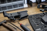
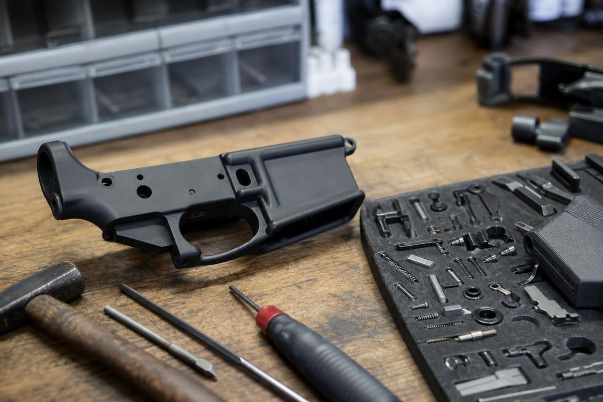
Building an AR-15 lower receiver is one of the most satisfying projects a shooter can take on, and knowing how to build an AR-15 lower receiver correctly from the start saves you time, money, and frustration. We stock the parts, lower parts kits, and complete uppers you need, all shipped from our Denison, TX facility. For assembly and function-check procedures, follow the receiver and parts manufacturers' instructions. Building your first lower? Shop stripped lowers, complete parts kits, and buffer assemblies ready to ship from Denison.
Key Takeaways
- Learning how to build an AR-15 lower receiver requires a stripped lower, a lower parts kit, a stock assembly, and basic hand tools.
- In Texas, there is no state waiting period, so a stripped lower transfer through an FFL can clear the same day your NICS check is approved.
- Assembly order matters: install the magazine catch, trigger guard, and bolt catch before fitting the trigger group, or follow the sequence specified by the receiver manufacturer.
- A complete upper assembly drops directly onto your finished lower with no additional fitting required when both are mil-spec.
What Do You Need Before You Start an AR-15 Lower Build?
You need four things: a stripped lower receiver, a lower parts kit, a buffer tube assembly with a stock, and a small set of hand tools. Everything else is optional. The parts lists below reflect a conventional lower build, but kit contents and receiver requirements vary by manufacturer.
The Stripped Lower Receiver and FFL Transfer
A stripped or complete lower assembly is a serialized firearm and must be transferred through a licensed FFL. Nonserialized parts may generally ship directly, subject to current federal, state, local, and dealer requirements. Transfer timing depends on purchaser eligibility, the background-check response, and dealer policy. Firearms purchased from us ship to the buyer's chosen FFL for transfer. Confirm your dealer's transfer fee before you order online.
Lower Parts Kit
Lower-parts-kit contents vary. Compare the included components with your receiver and build requirements before ordering. It does not include the buffer tube assembly or stock. Those are a separate purchase. A standard mil-spec LPK includes:
- Trigger, hammer, and disconnector
- Trigger and hammer pins
- Trigger spring and hammer spring
- Safety selector and detent
- Safety selector spring
- Bolt catch, bolt catch plunger, bolt catch spring, and roll pin
- Magazine catch, magazine catch button, and magazine catch spring
- Trigger guard and its retaining pin
- Pivot pin, takedown pin, and their detents and springs
- Buffer retainer and buffer retainer spring
- Pistol grip screw and lock washer
Check your kit against this list before you start. A missing detent or spring will stop the build cold.
Missing a part or starting fresh? Shop complete mil-spec lower parts kits with every detent, spring, and pin accounted for.
Buffer Tube Kit Components
The buffer tube kit is a separate purchase from the LPK. You need a receiver extension (buffer tube), buffer, buffer spring, castle nut, and end plate. Know whether your stock requires a mil-spec or commercial buffer tube before you order. Mil-spec and commercial carbine receiver extensions have different outside profiles and diameters, so the stock body must match the tube specification. If you have not settled on a stock yet, decide on your stock and buffer setup together so the two match.
Tools Required
Do not start without the right tools. Using the wrong tool or failing to support the receiver ear can damage the lower at the trigger-guard pin. That is a permanent mistake on an aluminum lower.
- Lower vise block and bench vise
- Roll pin punch set: 1/16-inch, 3/32-inch, and 1/8-inch
- Hammer and small rubber mallet
- Trigger-guard installation tool or punch specified by the receiver and guard manufacturers
- Pivot pin installation tool or small punch
- Armorer's wrench
- Torque wrench
- Needle-nose pliers
Use the trigger-guard installation tool specified by the receiver and guard manufacturers, and support the correct receiver ear during installation.
How Do You Install the AR-15 Magazine Catch?
Install the magazine catch by seating the catch body from the left side of the lower, then threading the spring and button on from the right until the catch sits flush. It is one of the first components you install in the lower build process, and getting it wrong causes feeding failures on every range trip.
Installing the Magazine Catch Button and Spring
Drop the magazine catch into the left side of the receiver and hold it in place with your left thumb. On the right side, slide the spring over the button post, then thread the button clockwise into the catch body. Use your right thumb to press the button inward while you turn. This keeps tension on the spring and lets the threads engage without cross-threading.
Keep threading until the catch face sits flush with the left side of the receiver, or just barely proud, no more than 1/16 inch.
Setting the Correct Thread Depth
Over-threading is the most common mistake here. If you thread the button too deep, the catch binds against the receiver wall and magazines will not seat or drop free cleanly. Back off one half-turn and retest.
Test by inserting an empty magazine and pressing the release button. The magazine should drop free with no resistance. If it sticks, the catch is threaded too far in. Adjust and retest before moving to the next step.
Trigger Guard Assembly
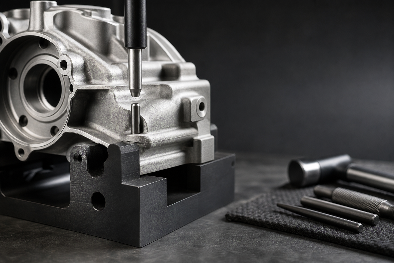
This is the step that breaks lowers. The retaining pin ears on most stripped lowers are thin aluminum, and one unsupported hammer strike can crack them clean through. Do not skip the support step. It is the most common damage point in any AR-15 lower assembly, and beginners skip it constantly.
Seating the Trigger Guard Roll Pin
Before driving the roll pin on a conventional removable trigger guard, support the rear receiver ear from below. Follow the receiver and trigger-guard manufacturers’ directions for the exact attachment design. Without that support, the ear flexes and cracks under impact.
Use the punch size and installation direction specified by the receiver and trigger-guard manufacturers. If you feel resistance mid-drive, stop. Check alignment before continuing. A misaligned pin will split the ear before it seats. Once the pin is flush, verify it is centered and the trigger guard rotates freely.
Integral vs Removable Trigger Guard Lowers
Some lowers come with an integral trigger guard machined directly into the receiver. If yours is one of those, skip this step entirely. There is no pin to drive and no cracking risk. Check your lower before you pick up a punch.
Removable trigger guards do have one real advantage. You can swap in an oversized winter trigger guard for gloved shooting. For cold-weather shooting, that is worth considering when you select your kit. Once your lower is complete, pairing it with a 5.56 NATO complete upper or a 300 Blackout complete upper gives you a ready-to-run rifle.
How Do You Install the Bolt Catch on an AR-15 Lower?
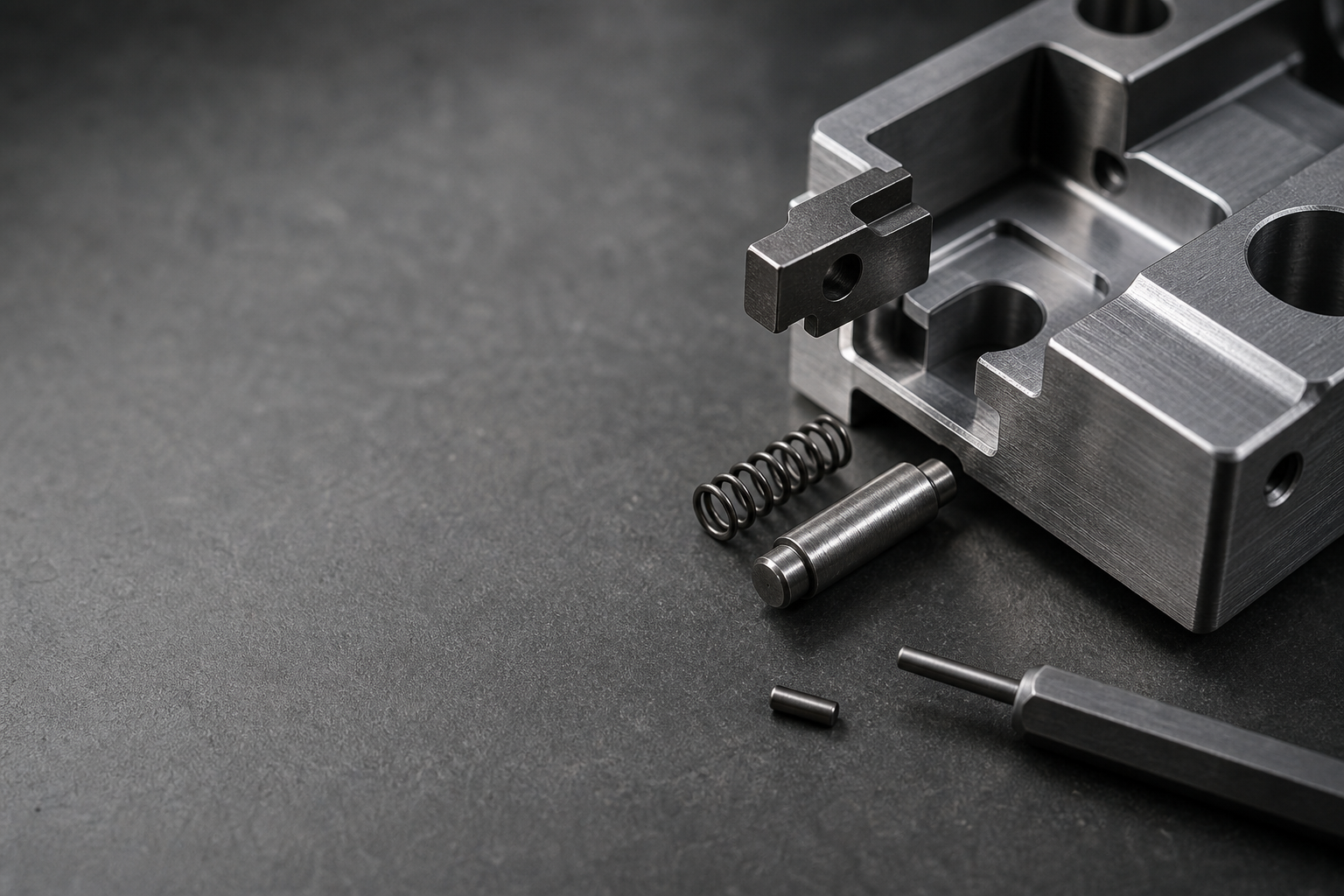
Install the bolt catch by dropping the spring and plunger into the recess on the left side of the lower, seating the catch body over them, and driving the roll pin in the direction specified by the receiver manufacturer. This sub-assembly has more failure points than any other stage of the build, and getting the order wrong means pulling the whole thing back apart. The bolt catch works directly with your bolt carrier group, so a misinstalled catch means the rifle will not hold open on an empty magazine.
Installing the Bolt Catch Plunger and Spring
Drop the spring into the bolt catch recess on the left side of the lower first. Set the plunger on top of the spring. Hold the plunger down with your thumb or a small punch and position the bolt catch body over the recess so it captures the plunger. Do not release pressure until the catch body is seated against the receiver.
If the plunger is not seated under the catch body before you drive the roll pin, the catch will not spring back. That means full disassembly and starting over.
Driving the Bolt Catch Roll Pin
Use a 3/32-inch roll pin punch. Drive the pin in the direction specified by the receiver manufacturer. Support the right side of the bolt catch with your finger or a block to keep it from rotating under the hammer strike. Drive the pin until it is flush on both sides. A proud pin will prevent your upper receiver from seating fully on the lower.
After the pin is seated, press the bolt catch and release it. It should spring back freely with no binding. If it sticks, the plunger is not seated correctly under the catch body.
Trigger Group Assembly
The trigger group is the most mechanically precise sub-assembly in the entire lower assembly sequence. Orientation errors here cause failures that are hard to diagnose after the fact. Before you start, decide whether you are running a single-stage or two-stage trigger, because the installation steps below apply to mil-spec single-stage triggers. Two-stage units may vary.
Installing the Trigger and Disconnector
Seat the disconnector spring into the pocket on the top of the trigger body. Install the disconnector coil spring in the manufacturer-specified orientation. Set the disconnector on top of the spring and confirm that it moves freely under spring tension.
Orient the trigger so the hook faces rearward, toward the buffer tube end of the receiver. Drive the trigger pin right to left, capturing both the trigger and disconnector in a single pass. Once seated, verify the disconnector rotates freely under spring tension. If it binds, the spring is not seated correctly.
Installing the Hammer
Compress the hammer spring legs around the trigger pin before you drop the hammer into the receiver. The legs must rest on top of the trigger pin. This is a mandatory check. Legs that fall behind the trigger pin will prevent trigger reset entirely, and the rifle will not function.
Drive the hammer pin right to left. Control the hammer by hand and verify its movement using the manufacturer-approved function-check procedure so it cannot strike the receiver. If it does not spring back, pull the assembly and recheck the hammer spring leg position.
Verifying Reset and Function
Run a dry function check before moving to the next stage of the build. Cock the hammer. Pull the trigger and hold it rearward. With the trigger still held, re-cock the hammer by hand. Now release the trigger slowly. You must hear and feel a distinct click as the disconnector transfers the hammer to the sear. If that click does not happen, stop. Do not proceed. Recheck spring orientation and pin seating before continuing.
Ready to add a buffer tube and stock? Browse stocks and check product details for compatible buffer tube kits.
Safety Selector, Takedown Pins, Pistol Grip, and Receiver Extension
Sequence matters in this stage more than any other. If you install the pistol grip before the safety selector, you will have to remove it again to correct the detent installation. Follow this order exactly and this stage of the build goes smoothly.
Installing the Safety Selector and Detent
Set the lower on your bench with the trigger group already installed. Install the safety selector and selector detent in the locations and orientation specified by the receiver manufacturer. The detent should seat against the selector’s detent groove. Do not install the grip yet. The grip traps the detent spring, and you need that access open for the next step.
Front and Rear Takedown Pins
The pivot pin installs from the right side. Drop the detent and spring into the detent hole in the lower's front lug, then use a pivot pin tool or a small punch to compress the detent while you push the pivot pin through from right to left. Install the rear takedown pin, detent, and spring according to the receiver manufacturer’s separate instructions. Both pins should move freely and remain retained in their intended positions. If either pin binds or fails to return, the detent is not seated correctly.
Pistol Grip and Safety Detent Spring
Place the safety detent spring into the hollow cavity inside the pistol grip. Align the grip over the lower so the spring seats into the detent hole above the grip screw hole. Thread the grip screw in by hand first, then torque to 45 to 65 in-lbs. Do not exceed this on polymer grips. Over-torquing cracks the grip around the screw boss.
Buffer Tube, Castle Nut, and Buffer Installation
Thread the end plate and castle nut onto the mil-spec buffer tube before you thread the tube into the lower. Thread the receiver extension forward until its lip properly captures the buffer retainer and spring. Follow the receiver-extension, end-plate, and castle-nut manufacturers’ torque and staking specifications for the exact parts being installed. Under recoil, an unstaked castle nut will back off and tie up your action.
Final Function Check and Pairing Your Lower with a Complete Upper
Before you attach any upper, you need to confirm the lower is working correctly. A completed lower that fails the function check has an assembly error. Find it now, not at the range.
Four-Step Function Check
Run the lower-receiver function check with no ammunition present and the upper removed. Control the hammer throughout the check so it cannot strike the receiver.
- Safety on SAFE, pull trigger. The hammer must not fall.
- Safety on FIRE, pull trigger. The hammer must fall cleanly.
- Hold trigger rearward, cock the hammer manually. The disconnector must catch the hammer, not the sear.
- Release the trigger slowly. You must hear and feel the reset click, and the hammer must transfer to the sear.
All four steps must pass. If any step fails, go back to your trigger group assembly. Do not move forward with a lower that does not pass this check.
Choosing a Complete Upper
A standard AR-15 lower supports many compatible upper and caliber configurations, but magazine, buffer, bolt, receiver, and manufacturer requirements can vary. The upper determines the barrel, gas system, and much of the caliber configuration. For a standard build, a 5.56 NATO complete upper is the most practical starting point. For a suppressed or subsonic setup, a 300 Blackout complete upper is the right call. Before you order, match your gas system length to your buffer setup so the upper you pick cycles reliably.
Customers nationwide can order complete uppers shipped directly to their door. Complete upper receiver assemblies are generally nonserialized components, but buyers should confirm current federal, state, local, and seller requirements before ordering.
Ordering an AR-15 Lower Online: Purchasing Notes
There are a few purchasing details worth knowing before you order a lower online. Federal law classifies the stripped lower as a firearm, regardless of what other parts you buy. That means it cannot ship directly to your door.
FFL Transfer Requirements for Online Buyers
Any serialized lower purchased online must ship to a licensed FFL dealer. The transfer process and timing depend on current law, purchaser eligibility, the background-check response, and dealer policy.
Serialized lowers purchased from us ship to the buyer's chosen FFL for transfer. Call us at (888) 706-0633 with any questions about the process.
Ordering Parts Online
Serialized stripped lowers and complete lower assemblies require FFL transfer. Nonserialized components such as parts kits, buffer assemblies, grips, and stocks may generally ship directly, subject to current federal, state, local, and seller requirements. That includes your parts kit, buffer tube kit, pistol grip, and stock.
We ship parts nationwide from our Denison, TX facility. Check current availability and estimated shipping times before ordering. Once your lower is assembled and function-checked, it can pair with a compatible upper. We carry complete AR-15 uppers for compatible lower receivers.
This section covers the general transfer process as a factual reference, not legal advice. Contact your FFL dealer directly with questions specific to your situation.
Frequently Asked Questions
Do I need an FFL to buy a stripped lower receiver?
A serialized stripped lower receiver must be transferred through a licensed FFL. Transfer procedures and timing depend on current law, purchaser eligibility, the background-check response, and dealer policy.
What is the correct assembly order for an AR-15 lower?
Start with the magazine catch, then the trigger guard, then the bolt catch. Install the trigger group next, followed by the safety selector. The pistol grip must go on after the safety selector because the grip screw hole captures the safety detent and its spring. Finish with the takedown pins and buffer tube assembly.
What tools do I actually need for an AR-15 lower receiver build?
Your core tools are a lower vise block, bench vise, roll pin punch set in 1/16-inch, 3/32-inch, and 1/8-inch, a hammer, an armorer's wrench, and a torque wrench. The one specialty tool worth buying is a trigger guard punch block. Without it, driving the retaining pin can crack the lower ears. That repair is expensive. The block is a small investment compared with replacing a damaged receiver.
Will any lower parts kit work with any stripped lower?
A mil-spec-pattern lower parts kit is designed for compatible mil-spec-pattern receivers, but manufacturer specifications and tolerance differences must be checked before installation. Billet lowers can have dimensional differences, particularly around the trigger pocket and pin holes. If your lower is billet, verify compatibility with the manufacturer before ordering a non-standard LPK. Confirm compatibility and complete the manufacturer-approved function check before use.
What is the difference between a mil-spec and commercial buffer tube?
Mil-spec buffer tubes measure approximately 1.148 inches in outer diameter. Commercial tubes measure approximately 1.168 inches. The difference is small but it determines which stocks fit. Choose your tube first, then match your stock to it.
How do I verify my completed lower is functioning correctly?
Run the four-step mil-spec function check before pairing with any upper. All four steps must pass. If the trigger resets incorrectly or the hammer follows the bolt carrier down, disassemble and check your trigger group spring orientation. A reversed disconnector spring is the most common cause of a failed function check on a first build.
We offer complete AR-15 uppers for compatible lower receivers. Browse 5.56 NATO complete uppers and 300 Blackout complete uppers online. Our complete uppers are built to order, assembled in-house, headspaced and function-checked before shipping. For questions, call us at (888) 706-0633 or contact our team.
Ready to Get Started with AR15Parts.com?
Call (888) 706-0633 to speak with our team directly. We can answer questions about parts and compatibility by phone or through our contact form.